- #Autocad electrical symbols pro#
- #Autocad electrical symbols windows 7#
- #Autocad electrical symbols download#
The generic Revit family will be able to form the central electrical distribution point of your digital model. Go to PowerPack for Revit, CAD to RFA converter and select the linked file using a …. The list contains all of the available distribution systems that match the voltage specification of the panel or transformer, ordered according to distance from the load (closest at the top).
#Autocad electrical symbols download#
#Autocad electrical symbols windows 7#
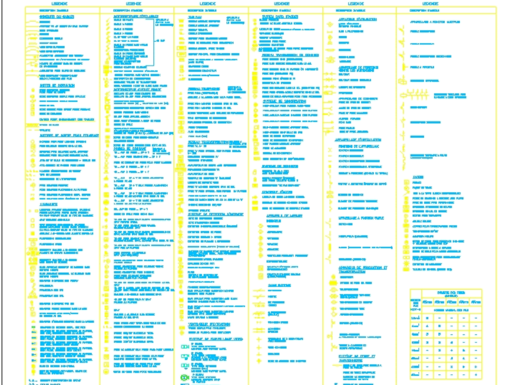
Windows 7 8 98 2000 vista.As I suspected! A simpler, more robust solution to the scissor arm transformer is achievable with a little trig. With smartdraw you can create more than 70 different types of diagrams charts and visuals. Free electrical symbols block and drawings for design block diagram wiring system architecture and more autocad drawing in dwg file formats for use with autocad and other 2d and 3d design software.

This channel is dedicated to sharing electrical engineering construction technical skills knowledge with people from all over the globe. Moving from autocad to autocad electrical guide.

Free electrical symbols for visio autocad svg and qelectrotech perfect for do it yourself during renovation or construction of your home. Autocad electrical difference between cad and cade cad electrical tells about the basic advantages of autocad electrical over normal cad.

Each diagram should include all equipment corresponding to a bay with breakers disconnectors and transformers represented by schematic symbols. Many converts to autocad electrical are coming from the plain autocad environment so there drawings usually consist of simple lines and text to represent wires and wire numbers and simple blocks to represent schematic symbols. Converting plain legacy autocad drawings to autocad electrical format.
#Autocad electrical symbols pro#
Ez schematics pro absolutely the simplest to use cad software program for developing electrical schematics and electrical line diagrams hydraulic and pneumatic schematics and diagrams motor control. A circuit diagram is a visual display of an electrical circuit using either basic images of parts or industry standard symbols.

Symbol usage depends on the audience viewing the diagram. The layout of ac connections diagrams should be carried out observing the following points.Įlectrical wiring diagram symbols in autocad.


 0 kommentar(er)
